What Should the Voltage Reading Be on B+ Post of Alternator

The 4 simple machine voltage current regulator circuits explained beneath is created as a immediate alternative to whatever standard regulator and, although developed principally for a dynamo it will function equally finer with an alternator.
If the functioning of a traditional auto alternator voltage regulator is analyzed, we find it astonishing that these kinds of regulators is often equally trusted as they are.
While most gimmicky cars are furnished with solid-state voltage regulators to regulate the voltage and current output from the alternator, you may still find countless earlier cars installed with electromechanical blazon of voltage regulators that happen to exist potentially unreliable.
How Electro-Mechanical Car Regulator Work
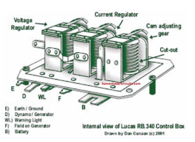
The standard performance of a electro-mechanical car alternator voltage regulator tin can be as explained below:
Once the engine is in the idling manner the dynamo starts getting a field electric current through the ignition warning lamp.
In this position the dynamo armature remains unattached with the bombardment since its output is smaller compared to bombardment voltage, and the battery starts discharging through information technology.
As the speed of the engine begins increasing, the output voltage of the dynamo besides begins rising. Equally presently every bit information technology surpasses the battery voltage a relay is switched ON, connecting the dynamo armature with the battery.
This initiates the charging of the battery. In case the dynamo output goes up even more an additional relay is activated at around 14.v volts which cuts off the dynamo field winding.
The field electric current decays while the output voltage begins dropping right up until this relay deactivates. The relay at this indicate consistently switches ON/OFF repeatedly, sustaining the dynamo output at 14.5 V.
This action safeguards the battery from overcharging.
At that place's also a tertiary relay containing its coil winding in series with the dynamo output, through which the unabridged dynamo output current passes.
Once the safe output current of the dynamo gets dangerously high, may be due to over discharged battery, this winding activates the relay. This relay now detaches the field winding of the dynamo.
The office ensures that just the fundamental theory, and the specific circuit of the proposed auto voltage current regulator may accept different specs depending on a specific automobile dimensions.
1) Using Power Transistors
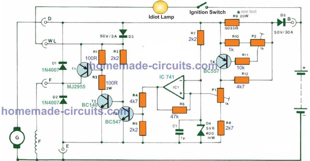
In the indicated blueprint the cutting-out relay is substituted past D5, which gets reverse-biased as before long equally the dynamo output drops below the battery voltage.
The battery as a result is unable to discharge into the dynamo. If the ignition is started upward the dynamo field winding gets electric current through the tell-tale light and T1.
Diode D3 is incorporated to avert current becoming drawn from the field curl due to the reduced armature resistance of the alternator. As the speed of the engine increases the output from the dynamo proportionately rises, and starts delivering its own field current by means of D3 and T1.
Every bit the cathode side voltage of D3 goes up the alert calorie-free gradually dims until information technology fades off.
When the dynamo output reaches to around 13-14 V the battery begins charging over again. IC1 works like a a voltage comparator which tracks the dynamo output voltage.
Equally the dynamo output voltage increases the voltage on the op amp inverting input is at showtime greater than at the non-inverting input, hence the IC output is held low and T3 remains switched off.
As presently as the output voltage goes college than v.6 V the inverting input voltage is regulated and controlled at this level by D4.
When the output voltage goes past the specified highest potential (set through P1), the not-inverting input of IC1 becomes higher than the inverting input, causing the IC1 output to change into positive. This activates T3. which switches OFF T2 and T1, inhibiting current to the dynamo field.
The dynamo field current now decays and the output voltage begins dropping until the comparator reverts back again. R6 supplies several hundred millivolts of hysteresis which helps the excursion to work like a switching regulator. T1 is either toggled harder ON or is cut off such that information technology dissipates adequately low power.
Electric current regulation is impacted through T4. One time the current by ways of R9 is higher than the selected highest level, the voltage drop around it results in T4 to switch on. This raises the potential at the non-inverting input of IC1 and isolates the dynamo field current.
The value selected for R9 (0.033 Ohm/twenty W, made up of 10nos of 0.33 Ohm/2 Westward resistors in parallel) is suitable to become a optimum output current as high as xx A. If larger output currents is desired, R9 value could be reduced appropriately.
The output voltage and current of the device must be stock-still by accordingly setting up P1 and P2 to meet the standards of the original regulator. T1 and D5 should exist installed on heatsinks, and must exist strictly isolated from the chassis.
two) A Simpler Car Alternator Voltage Current Regulator
The following diagram shows another variant of a solid country car alternator voltage and current controller circuit using minimum number of components.
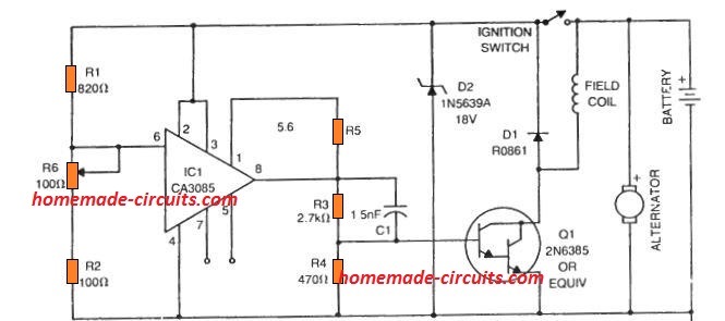
Commonly while the battery voltage is below, the full charge level, the regulator IC CA 3085 output remains switch OFF, which allows the Darlington transistor to be in the conducting mode, which keeps the field coil energized, and the alternator operational.
Since the IC CA3085 is rigged equally a bones comparator here, when the battery charges to its full charge level, may ba 14.two 5, the potential at pivot#6 of the IC changes to 0V, switching OFF the supply to th field scroll.
Due to this the electric current from the alternator decays, inhibiting whatever further charging of the battery. The battery is thus stopped from overcharging.
Now, as the battery voltage drops beneath the CA3085 pin6 threshold, the output becomes high over again, causing the transistor to bear, and ability the field roll.
The alternator begins supplying to the battery, so that it begins charging over again.
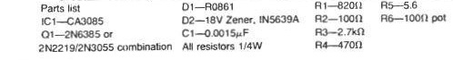
Parts List
iii) Transistorized Automobile Alternator Regulator Circuit
Referring lo the nest solid-country alternator voltage current regulator diagram beneath, V4 is configured like a series-pass transistor which regulates the current to the field of the alternator. This transistor along with the two 20 amp diodes are clamped on an external heatsink. It is intriguing to see that dissipation of V1 is not really very high even during the maximum field current, rather just within 3 amps.
However, instead of the mid-range at which the voltage drop beyond the field is corresponding to that of transistor V1 causing a highest dissipation of not more x watts.
Diode D1 provides protection to the pass transistor V4 from the inductive spikes generated within the field scroll any time the ignition switch is switched off. Diode D2 which transfers the entire field current supplies extra working voltage for driver transistor V2 and guarantees that the laissez passer transistor V4 could be cut-off at large groundwork temperatures.
Transistor V3 works like a driver for V4 and a base-current swing of iii ma to five ma upon this transistor allows full "on" to full "off" switching of V4.
Resistor R8 offers a road for the current during excessive temperatures. Capacitor C1 is essential to protect against oscillation of the regulator because of the loftier gain loop that is created around the the system. A Tantalum capacitor is recommended hither for increased precision.
The primary element of the command-sensing circuit is enclosed within the balanced differential amplifier consisting of transistors V1 and V2. Special concern had been provided to the layout of this alternator regulator is to make certain there is no temperature drifting issues. To attain this nigh linked resistors must be wire-wounds types.
The voltage control potentiometer R2 deserves specific consideration as it should never motion away from its settings due to vibrations or temperature farthermost conditions. The 20-ohm pot employed in this blueprint worked ideally well for this program still virtually every good Wirewound pot in the rotary style might exist just fine. The rectilinear trimpot varieties must exist avoided in this machine alternator voltage current regulator design.
4) IC 741 Motorcar Alternator Voltage Current Regulator Charger Circuit
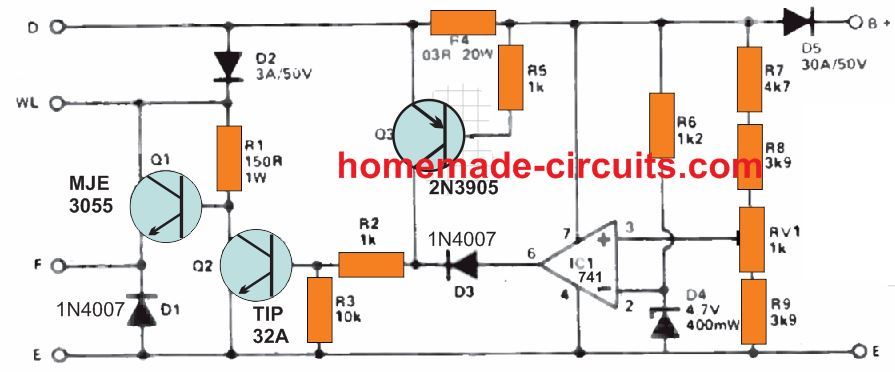
This circuit offers solid-land direction of battery charging. The alternator's field winding is in the commencement stimulated through the ignition calorie-free seedling but as in a traditional method.
Current moving across the WL terminal travels via Q1 to the F final then finally on the field ringlet. Every bit soon as the engine is powered, current from car'due south dynamo moves through D2 to Q1. The ignition tell-tale lamp fades out since the WL terminal voltage exceeds than that of the battery. Current likewise moves through D5 towards the battery.
At this indicate, IC1 which is rigged as a comparator detects the battery voltage. When this voltage on the not-inverting input becomes higher than the inverting input (clamped at 4.6 volts via zener D4) causes the output of the op amp to become high.
Current subsequently passes via D3 and R2 towards the Q2 base of operations and instantly switches information technology ON. This activeness every bit a consequence grounds the Q1 base switching it off and removing the current applied on the field winding. The alternator output at present drops, causing battery voltage to besides drop correspondingly.
This procedure ensures that the battery voltage is always held constant, and is never allowed to be over charged. The bombardment full charge voltage can be tweaked through RV1 to roughly thirteen.5 volts.
During common cold conditions conditions while starting the auto, the bombardment voltage may drops significantly low. As soon as the engine has ignited the bombardment's internal resistance likewise become quite low, forcing it to pull too much current from the alternator and thus leading to a possible deterioration of the alternator. In order to restrict this loftier electric current consumption, resistor R4 is introduced inside the chief ability terminal from the alternator.
The R4 resistance is selected making sure that at highest possible electric current (Commonly 20 amps) 0.six volts is generated across it which causes Q3 to plough ON. The moment Q3 activates current moves through the power line through R2 towards the Q2 base of operations, switching it on, which then, shuts off Q1 and cutting off current flow to the field winding. Due to this the dynamo or the alternator output now drops.
No modifications need to exist made to the original wiring of the alternator in the car. The circuit could be encased within an old regulator box, Q1, Q2 and D5 must be attached to an appropriately dimensioned heat sink.
fosternottlentimen.blogspot.com
Source: https://www.homemade-circuits.com/car-alternator-regulator-circuit/
0 Response to "What Should the Voltage Reading Be on B+ Post of Alternator"
Postar um comentário